
"Building" Wind Loads can be automatically generated per the following codes:
Note:
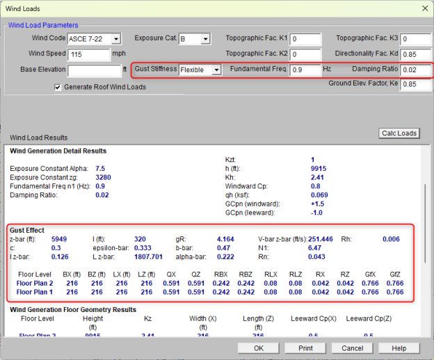
The parameters used for automated wind load generation may be viewed or changed
The parameters and results shown below are specific to ASCE 7-22, however the concepts apply to all wind codes. For questions specific to other wind codes contact RISA Technical Support.
Wind Speed (V) is used to calculate wind pressures. See ASCE 7-22, Section 26.10.2
Exposure Category is used for multiple wind load calculations, and is defined in ASCE 7-22, Section 26.7.3
Base Elevation defines the elevation that the program considers as the "ground elevation". This is typically used for structures which have basements, or base coordinates other than 0.
Gust Stiffness is used in the calculation of the Gust Effect Factor. See ASCE 7-22, Section 26.11. (NOTE: This is only available for ASCE 7-22, ASCE 7-16 & ASCE 7-10).
Fundamental Frequency is used in the calculation of the Gust Effect Factor and can be modified when the Gust Stiffness is set to Flexible.
Damping Ratio is also used in the calculation of the Gust Effect Factor. This option will appear and can be modified when the Gust Stiffness is set to Flexible.
Gust Factor (G) is explained in ASCE 7-22, Section 26.11 and depends on the Gust Stiffness setting. See Gust Effect Factor.
Topographic Factors (K1, K2, K3) are used to calculate the Topographic Factor (Kzt) per ASCE 7-22, Section 26.8.2.
Directionality Factor (Kd) is used to calculate wind pressures. See ASCE 7-22, Section 26.6.
Ground Elevation Factor (Ke) is calculated per ASCE 7-22, Section 26.9 using Table 26.9-1 (note: Per ASCE 7-22, Section 26.9, Ke is permitted to equal 1 for all elevations). This option will appear and can be modified when ASCE 7-22 or ASCE 7-16 is selected.
Generate Roof Wind Loads is only present in RISA-3D models which are integrated with RISAFloor. This toggles the automatic generation of sloped roof wind loads.
The program calculates the appropriate wind loads and presents the calculations in a printable report. You may open the wind load generator at any time to view, print or recalculate the wind loads.
Changes made to RISAFloor models which are integrated with RISA-3D models will be reflected in automatically updated wind loads when transferring between the programs.
This section reports values which were directly or indirectly input from the Wind Load Parameters.
This section reports important values that were calculated using the Wind Load Parameters, as well as the height and base elevation of the structure.
Importance Factor is calculated using the input Occupancy Category.
Exposure Constant Alpha (α) is determined from ASCE 7-22, Table 26.11-1 based on the input Exposure Category.
Exposure Constant zg is determined from ASCE 7-22, Table 26.11-1 based on the input Exposure Category.
Topographic Factor (Kzt) is calculated per ASCE 7-22, Section 26.8.2 using the input Topographic Factors (K1, K2, K3)
Ground Elevation Factor (Ke) is calculated per ASCE 7-22, Section 26.9 using Table 26.9-1 (note: per ASCE 7-22, Section 26.9 Ke is permitted to equal 1 for all elevations)
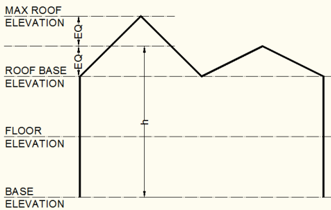
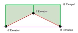
Mean Roof Height (h) is determined as illustrated below:
Exposure Coefficient (Kh) is calculated per ASCE 7-22, Table 26.10-1 at the mean roof height as illustrated above. The Exposure Constants (zg, α) are used in conjunction with the formula in Table 26.11-1, Note 1 to calculate the Exposure Coefficient.
Windward Pressure Coefficient (Cp) is calculated per ASCE 7-22, Figure 27.3-1. The wind load generator always sets this value at 0.8 per ASCE 7-22, Figure 27.3-1.
Mean Roof Velocity Pressure (qh) is calculated per ASCE 7-22, Section 26.10.2. The input Directionality Factor and Wind Speeds are used.
Parapet Wind Pressure Coefficient (GCpn) is calculated per ASCE 7-22 Section. 27.3.4 for both windward and leeward directions.
When the Gust Stiffness is set to Flexible, this section reports the values used in the calculation of the gust effect factor.
Gust Effect Factor(G) is explained in ASCE 7-22, Section 26.11. Gust Effect Factor depends on the Gust Stiffness input setting (NOTE: This is only available for ASCE 7-22, ASCE 7-16 & ASCE 7-10).
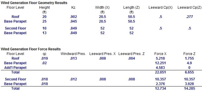
The wall geometry used to calculate the wind loads is reported here.
Floor Level is the name of the Floor from RISAFloor. Multiple diaphragms on the same floor will each be reported separately. For sloped wall calculations the level will always be reported as "Sloped Roof".
Height is the height of each diaphragm above the input Base Elevation. For "Sloped Roof" floors from RISAFloor the height reported is the height of the highest point in each diaphragm.
Exposure Coefficient (Kz) is the calculated exposure coefficient at the diaphragm elevation. For "Sloped Roof" floors from RISAFloor the coefficient is calculated for the highest point in each diaphragm.
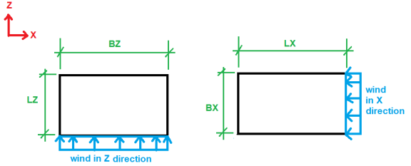
Width is calculated as the difference between the highest and lowest magnitude X-Coordinates on the diaphragm.
Length is calculated as the difference between the highest and lowest magnitude Z-Coordinates on the diaphragm.
Pressure Coefficient (Cp) is calculated per ASCE 7-22, Figure 27.3-1. The Height/Width and Height/Length ratios (see above) are used to calculate leeward pressure coefficients.
If the level considered is not sloping and does not have a parapet then the results here will be a single line.

If a parapet exists at this level, then information regarding the parapet will be given as well.

If this level is sloping then there may also be a section giving the wind face information due to this sloping portion.

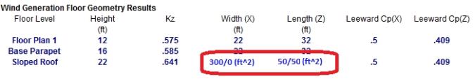
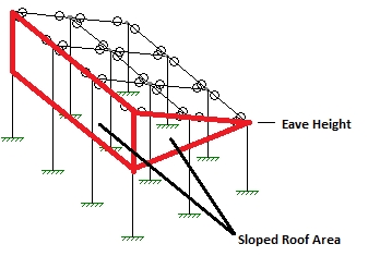
Sloped Roof Area is used to account for the wind load on walls which project above the base roof elevation due to a sloping roof. This only occurs in models which are integrated with RISAFloor. The program determines area by going from support-to-support finding vertical polygons along the slab edge, and calculating their projected area in both the X and Z directions.
The area reported is the windward followed by leeward.
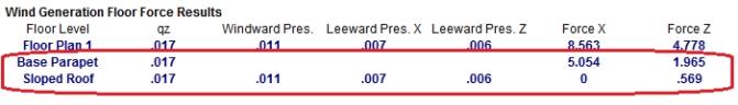
The wind forces applied to each diaphragm are reported in this section.
Floor Level is the name of the Floor from RISAFloor. Multiple diaphragms on the same floor will each be reported separately. For sloped wall calculations the level will always be reported as "Sloped Roof".
Velocity Pressure (qz) is calculated per ASCE 7-22, Section 26.10.2. The input Directionality Factor and Wind Speeds are used.
Windward Pressure is calculated per ASCE 7-22, Section 27.3.1. The calculated Velocity Pressure and Pressure Coefficient are used, as well as the standard Gust Effect Factor (0.85).
Leeward Pressure is calculated per ASCE 7-22, Section 27.3.1. The calculated Velocity Pressure and Pressure Coefficient are used, as well as the standard Gust Effect Factor (0.85).
Force is calculated as the Length/Width (see above) of the diaphragm, multiplied by the tributary height of the diaphragm, multiplied by the sum of the windward and leeward pressures. The additional "Sloped Roof" wall wind force in RISAFloor integrated models is also added to this value for the Roof.
The tributary height of the diaphragm is defined as half the distance the diaphragm immediately above, and half the distance to the diaphragm immediately below. At the roof the tributary height is just half the distance to the diaphragm immediately below. At the lowest level of the structure the tributary height is half the distance to the Base Elevation, as it is assumed that all wind load below that is tributary to the ground.
The Forces calculated for each diaphragm are applied as horizontal joint loads at the center of exposure, and four "eccentric" points (per ASCE 7-22, Section 27.3.5). These joints form a diamond pattern, which can be viewed in the model.
If the level considered is not sloping and does not have a parapet then the results here will be a single line.


If a parapet exists at this level, then information regarding the parapet (and possibly the additional height of multiple height parapets) will be given as well and the total force due to both the main wind force and the parapet wind force will be summed.
If this level is sloping then information regarding the sloping area will be given as well and the total force due to both the wind force below the eave and the wind force above the eave will be summed.

Note:
When RISA-3D is integrated with RISAFloor then it is possible to define parapets for both wall panels and columns. After parapets are defined the wind load generator will use these parapet heights to add additional wind loading to the roof levels of your structure to include this parapet wind with the roof wind load. The total wind force, including all parapets and the non-parapet wind, will be applied at the center of wind location in RISA-3D. Here we will give some details as to how this works.
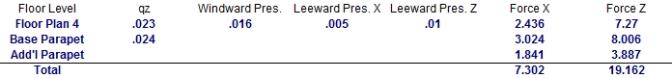
The reporting was outlined above. However, the program will also give a Parapet Summary as well.
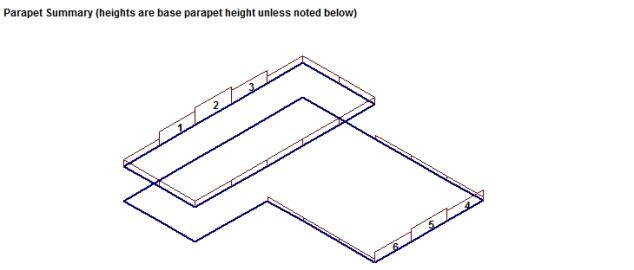
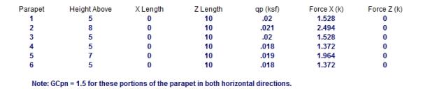
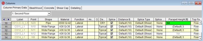
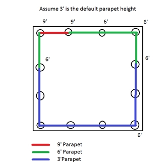
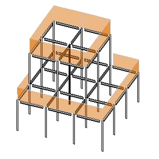
In this image you can see (to scale) where all the parapets in your structure are located. The base parapet information has already been considered in the Base Parapet, so the only parapet information listed below the image are for the parapets that extend above the Base Parapet. The GCpn for this portion of the parapets will be assumed to always be windward. Each of these parapets is shown with the extra force above and beyond the Base Parapet Height. The Force X & Z columns are once again added to the Base Parapet and the regular building wind to give the total wind applied at that floor level.
Note:
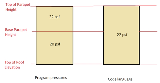
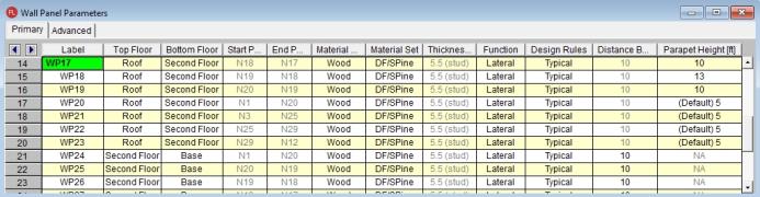
Parapet height information is located in three places: the Floors, Columns, and Wall Panels spreadsheets. If a floor has a Default Parapet Height set then all walls and columns at that level will have their parapet values set to that value. This is considered the Base Parapet.
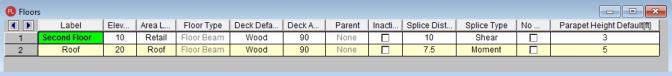
The walls and columns are physically extended. From here you can go to the Columns or Wall Panels spreadsheets if you need to extend parapets above this base level. These values are the Top of Parapet Height. If this value is higher than the Default Parapet Height then this component of win loading will show up in the Add'l Parapet entry.
Note:
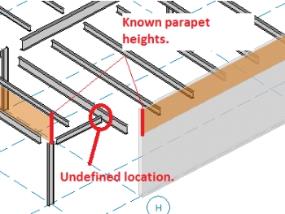
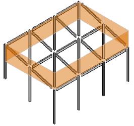
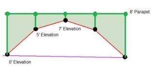
For walls a parapet is defined along a line that defines the top of the wall. Thus, the area of the parapet is trivial. For parapets defined by columns, however, we now have parapet heights at finite locations. In this case the program will go "column to column" around the structure to determine the parapet height. The parapet height used between columns is the SMALLER of the two values at each column. Below is an example of what this would look like.
Note:
Per the ASCE 7-22 Section 27.3.4, the velocity pressure at the top of the parapet shall be multiplied by a GCpn of +1.5 for windward parapets and -1.0 for leeward parapets.
Note:
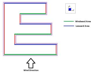
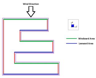
Most codes prescribe a higher pressure on the windward parapet than the leeward parapet. Thus, parapet wind loads may or may not be symmetric in each direction. The program will calculate the wind loads in both the positive and negative directions and use the larger of the two. For rectangular structures it is very simple to determine windward/leeward directions. However, a more complex structure can be more difficult. The image below gives one example of how windward/leeward parapets are considered.
|
|
Note:
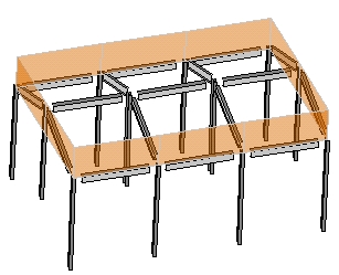
In RISAFloor it is possible to slope the highest level in a structure. This can create "wind faces" due to these slopes. Think of a monosloped structure. Above the eave you have triangular areas that are wind faces that the program already calculates appropriately. If there are additional parapets to consider that occur as well the geometry can become challenging.
Note that the program will look at both the +/- X and +/- Z directions to determine which direction has the higher force and that is the force that will be used in the program.
Note:
![]()
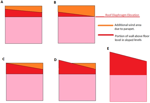
Here are some common conditions:
Here we have a sloping roof which will have perpendicular wind loads applied. This will occur. In addition there will be additional horizontal loads due to the parapet.
|
|
In this case the triangular face is taken as a regular wind load and the additional triangular/polygon loads that are due to the parapet (similar to Case A,B, or C) have their areas calculated and included as parapet loads.
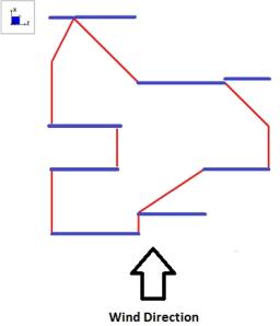
In this case there are triangular parapet wind areas on two sides (similar to Case C above) , a full parapet area on one side, and no parapet on the backside. In the triangular parapet direction the wind areas are equal in each direction thus the same value will occur in both directions. In the perpendicular direction the parapet is windward and the sloped area is leeward in the positive direction, and vice-versa in the negative direction. In this case the program will take the largest magnitude and apply it to your roof.
This is similar to the gabled with a slightly different geometry.
|
|
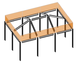
It is also possible to define partial roof parapets. The program will handle this scenario properly. Below we can see that we have a lower level with parapets defined around the edges. Thus, for some of the length of the parapet there is not a leeward parapet included.
You may designate any floor level as a mezzanine or "No Wind" level in the
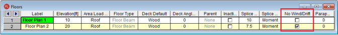
By checking this check box you are telling the program that the floor is to be ignored in the wind load calculations.
Note: When integrating a RISAFloor model into RISA-3D, this designation may only be set in the RISAFloor model. It will show up as greyed out/unavailable in RISA-3D for integrated models, so you must go back to RISAFloor of you want to change the selection.
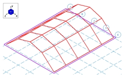
When RISA-3D is integrated with RISAFloor the program is capable of automatically calculating the perpendicular roof wind loads per ASCE 7-22, Figure 27.3-1. These loads are calculated using the mean roof height for each diaphragm, the standard Gust Effect Factor (0.85), and a Roof Pressure Coefficient (Cp) for each roof plane.
The angle (θ) for each roof plane is taken as the angle between the roof plane and the horizontal plane, as projected along the Global X and Z axes. To determine a Roof Pressure Coefficient the wind load is always assumed to act "Normal to Ridge" with θ not less than 10°. Roof planes that do not meet these conditions will still be treated as though they do.
Only the most positive values of Cp are used from the table in ASCE 7-22, Figure 27.3-1. The more negative values typically result in less base shear within the Main Wind Force Resisting System, so they are ignored. Interpolation is used between values given in the table.
The sloped roof wind loads are applied as two-way Member Area Loads to each roof plane, and are created within roof wind load Basic Load Cases.
For additional advice on this topic, please see the RISA Tips & Tricks webpage at risa.com/post/support. Type in Search keywords: Sloped Roofs.
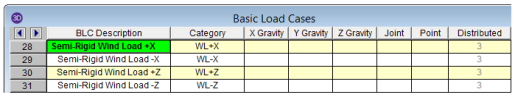
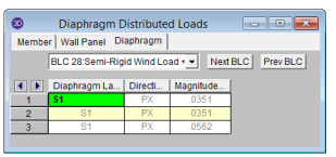
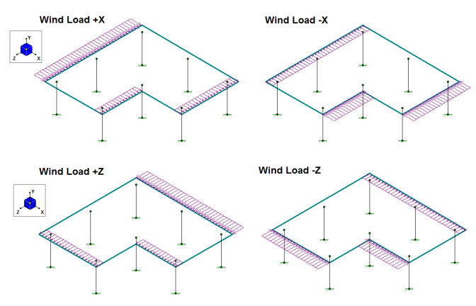
When RISA-3D is integrated with RISAFloor the program has the ability to create Semi-Rigid wind loads and apply them to the diaphragm.. The wind load is calculated by taking the Windward and Leeward forces and distributing it directly into the diaphragm as a linear load along the edge of the diaphragm. The Semi-Rigid Wind loads are placed into the Basic Load Cases shown below with distributed loads. The distributed loads are displayed per slab and the magnitude is shown but not editable. An example of the load distribution is shown on this L-shaped building.
Note:
Note:
Note: